Parallel CRC Generator
|
|
Download a full version of this article |
Every modern communication protocol uses one or more error detection algorithms. Cyclic Redundancy Check, or CRC, is by far the most popular one. CRC properties are defined by the generator polynomial length and coefficients. The protocol specification usually defines CRC in hex or polynomial notation. For example, CRC5 used in USB 2.0 protocol is represented as 0x5 in hex notation or as G(x)=x5+x2+1 in the polynomial. This CRC is implemented in hardware as a shift register as shown in the following picture.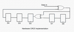
The problem is that in many cases shift register implementation is suboptimal. It only allows the calculation of one bit every clock. If a design has 32-bit wide datapath, meaning that every clock CRC module has to calculate CRC on 32-bit of data, this scheme will not work. Somehow this serial shift register implementation has to be converted into a parallel N-bit wide circuit, where N is the design datapath width, so that every clock N bits are processed.
I started researching the available literature on parallel CRC calculation methods and found only a handful of papers ([2], [3]) that deal with this issue. Most sources are academic and focus on the theoretical aspect of the problem. They are too impractical to implement in software or hardware for a quick code generation.
I came up with the following scheme that I’ve used to build an online Parallel CRC Generator tool. Here is a description of the steps in which I make use USB CRC5 mentioned above. 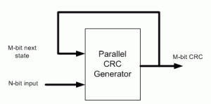
(1) Let’s denote N=data width, M=CRC width. For example, if we want to generate parallel USB CRC5 for 4-bit datapath, N=4, M=5.
(2) Implement serial CRC generator routine using given polynomial or hex notation. It’s easy to do in any programming language or script: C, Java, Perl, Verilog, etc.
(3) Parallel CRC implementation is a function of N-bit data input as well as M-bit current state CRC, as shown in the above figure. We’re going to build two matrices: Mout (next state CRC) as a function of Min(current state CRC) when N=0 and Mout as a function of Nin when M=0.
(4) Using the routine from (2) calculate CRC for the N values when Min=0. Each value is one-hot encoded, that is there is only one bit set. For N=4 the values are 0x1, 0x2, 0x4, 0x8. Mout = F(Nin,Min=0)
(5) Build NxM matrix, Each row contains the results from (3) in increasing order. For example, 1’st row contains the result of input=0x1, 2’nd row is input=0x2, etc. The output is M-bit wide, which the desired CRC width. Here is the matrix for USB CRC5 with N=4.
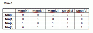
(6) Each column in this matrix, and that’s the interesting part, represents an output bit Mout[i] as a function of Nin.
(7) Using the routine from (3) calculate CRC for the M values when Nin=0. Each value is one-hot encoded, that is there is only one bit set. For M=5 the values are 0x1, 0x2, 0x4, 0x8, 0x10. Mout = F(Nin=0,Min)
(8) Build MxM matrix, Each row contains the results from (7) in increasing order. Here is the matrix for USB CRC5 with N=4
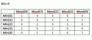 (9) Now, build an equation for each Mout[i] bit: all Nin[j] and Min[k] bits in column [i] participate in the equation. The participating inputs are XORed together.
Mout[0] = Min[1]^Min[4]^Nin[0]^Nin[3]
Mout[1] = Min[2]^Nin[1]
Mout[2] = Min[1]^Min[3]^Min[4]^Nin[0]^Nin[2]^Nin[3]
Mout[3] = Min[2]^Min[4]^Nin[1]^Nin[3]
Mout[4] = Min[0]^Min[3]^Nin[2]
That is our parallel CRC.
I presume since the invention of the CRC algorithm more than 40 years ago, somebody has already came up with this approach. I just coulnd’t find it and “reinvented the wheel”.
Keep me posted if the CRC Generation tool works for you, or you need more clarifications on the algorithm.
[September 29th, 2010] Users frequently ask why their implementation of serial CRC doesn’t match the generated parallel CRC with the same polynomial. There are few reasons for that:
– bit order into serial CRC isn’t the same as how the data is fed into the parallel CRC
– input data bits are inverted
– LFSR is not initialized the same way. A lot of protocols initialize it with F-s, and that’s what is done in the parallel CRC.
|
|
Download a full version of this article |
References
- CRC on Wikipedia
- G. Campobello, G Patane, M Russo, “Parallel CRC Realization”
- W Lu, S. Wong, “A Fast CRC Update Implementation”

Hello Evgeni, I’m posting this message to check if it will be shown immediately. Because I already posted a message before.
Tennirva
Hi everyone,
i’m currently working on an hardware implementation of crc32 algorithm using the 2-step method, but it seems that the functions given in this paper by A. Simionescu: “CRC Tool: Computing CRC in Parallel for Ethernet,” Nobug Consulting,
are not doing fine.
If i’m not missunderstanding, here is he thing:
Using a polynomial’s degree of 123, each intermediate values of CRC calculated on each clock cycles with incoming words are on 123 bits. the initial value of CRC must be (others=>’0′) using this methode. The huge advantage of this way to compute CRC is that on last word, you don’t have to pay attention on empty bytes, because either you have 0 or 1 or 2 … empty bytes, if your word is filled with ‘0’ where it’s empty, your final CRC value will be the same.
=> Much less logical elements used.
But, what is weird with functions given on this article, is that the final value of CRC isn’t generated properly.
Does anyone implemented these functions and did it worked fine on first try ?
Thanks in advance,
Fabien
Hi, if any body needs “CRC32 for 802.3″ with equal results whith this sites crc32 generator,
http://crc32-checksum.waraxe.us/
or
http://www.lammertbies.nl/comm/info/crc-calculation.html
can use crc_chk.v and crc_gen.v files at this opensource project:
https://opencores.org/project,ethernet_tri_mode
Regards Serjik.
hi ,site is really great especially for beginner like me.can any one tell how the reg value lfsr_q linked with crc_out and also what abt its initial value.
thanks
DG
Hi,
LFSR value is the same as CRC. Its initial value depends on the protocol.
Thanks,
Evgeni
Hi,
The article is really useful. Thanks alot.
A little question. Why do we use ONE HOT values for the two matrices input ?
Regards
Because it enables any combination of the input values.
Thanks,
Evgeni
Thanks for reply — (I am nearly half way to the correct understanding)
Does it means that — it mimics the behaviour of LFSR in a sense that : There is only one input to a CRC and it matters only when it is SET (=1) — & since it is a shift register it shifts towards the output.
@Evgeni
Hello Evgeni,
Thanks for the awesome Tool! I generated VHDL Code for a CRC5 for 20 Bits.
Where is my Mistake:
I feed a dataword into the data_in and do not change it.
crc_en is 0.
I feed a Clock into clk.
I set the rst to 1 for a few clock cycles and then to 0
after a few clocks I set crc_en to 1 and get the CRC at crc_out?
This CRC is fed back by the crc routine as new start-word?
When I get the next positive clk edge The Routine does the CRC-“check” and I should get the start-word as a result?
This is not the case 🙁
can you please help me?
Ludwig
Hi Ludwig,
When you feed back the current CRC value, the logic calculates the next CRC based on the current one and the data_in.
So it’s not the CRC for start word anymore.
If you want to calculate CRC for start word, you need to reset the CRC first.
Thanks,
Evgeni
Hi Evgeni,
Thank you for the quick response!
Okay I understand, that I have to reset before each crc computation.
So I put my data into data_in, reset, enable, and get my CRC. That works.
I transmit both to the receiver.
How do I check for correct Transmission on the receiving end?
In other words: how do I feed Data and CRC into the Routine to get the “00000”, which says, that there was no transmission error?
Thank you
Ludwig
Hi Ludwig,
You check CRC in a similar way you generate it. Pass the received data thru the CRC module and then compare with the expected CRC.
Thanks,
Evgeni
Hello Evgeni,
I really need help to Implement CRC for a system which the data width is 1120 bit ( 140 bit) and the polynomial is order is 28 which is (x^28 + x^26 + x^24 + x^23 + x^18 + x^17 +x^16 + x^15 + x^14 + x^11 + x^8 + x^4 + x^3 + 1) or (1, 0, 1, 0, 1, 1, 0, 0, 0, 0, 1, 1, 1, 1, 1, 0, 0, 1, 0, 0, 1, 0, 0, 0, 1, 1, 0, 0, 1 ).
The online system does not work for that long data width.
Could you please, give the Verilog for the above CRC.
I appreciate your cooperation, and thanks in advance.
Majeed
* Correction: 1120 bit (140 byte)
Hi Majeed,
You can download a standalone application and source code for CRC generator from OpenCores
You can increase DATA_MAX_WIDTH from 1024 in the code to the size you need, then recompile.
Thanks,
Evgeni
Detail of my previous post:
Also the encoding is performed in a systematic form, which means that in GF(2), the polynomial:
(M1 X^k+27 + M2 X^k+26 + M1 X^k+25 +…..+ M^k X28 + p1 X^27 + p2 X^26 +…..+ p27 X^1 + p28)
where:Denote the bits in the input message by M1, M2 …Mk (K=1120 bit) and the parity bits by p1, p2,…,p28.
Evgeni,
Thanks so much.
Can I also Implement the above systematic form in the standalone application?
Hi Majeed,
I’m not familiar with the systematic form.
Thanks,
Evgeni
Evgeni,
Thanks so much. I appreciate your cooperation
Majeed
Hi..
I have downloaded the code from your website for 802.3 for 8 bit of data, 32 bit polynomial.
here i have few doubts.
1.CRC EN should be held high for complete data( means am sending 1478 bytes of data)
2.when i compare the CRC out with thw online CRC generators, the output is not matching?
3.The same check will be done at s/w application also, so they are asking give me polynomial number like that .. when i simulate your code by default the number will be “4E08BFB4” is it the one?
its very urgent required
Please reply me as early as possible
Hi,
1. CRC En should be held for the valid data
2. There are several possible reasons for the mismatch: byte and bit ordering, incorrect polynomial. I’d recommend reading earlier discussions on this thread.
Thanks,
Evgeni
Evgeni many thanks for this wonderfull tool!!!!
implemented 8 bit crc on 40 bit input with HD of 4.
CRC computation is instant (rising edge) and fully synthesizable!!!
perfect!!!
Hi Thomas,
Great to hear that you found the tool useful.
Thanks,
Evgeni
Hi Evgeni,
I want to implement CRC for modbus which uses CRC-16 ANSI or 0x8005 (normal form) & 0xA001 (reverse form). I used your tool but it isn’t giving correct output.
I initializeed CRC register to all 1’s (modbus specification).
Are there some additional operations needed to get the correct output?
for e.g. data = 0xFF CRC =0x00FF & data = 0x00 CRC =0x40BF (using modbus calculator)
Please reply me as early as possible
Ajinkya
Hi Ajinkya,
I most cases it’s a bit or byte ordering problem. Try to simplify the code; for example start with serial data (1 bit), instead of parallel.
Thanks,
Evgeni
Thanx Evgeni !!
It worked by reversing both data and crc registers.
It is a great tool for crc!! genius
In the pdf file, there seems a typo in the equation for CRC5:
It should be: Mout[0] = Min[1]^Min[4]^Nin[0]^Nin[3]
Instead, the doc says Mout[0] = Min[1]^Min[4]^Min[0]^Min[3]
Yes, there is a typo.
Correction is buried in the comments here:
http://outputlogic.com/?p=158&cpage=2#comment-1037
Hello sir,
I am currently working on a ethernet code where i need to implement a CRC32 module for 32 bit datain. Can you please guide me through it?
Thanks,
Musthaq
Hello Evgeni,
Well, i generated the verilog code for 802.3 protocol for 32 bit datain. Since I want to validate the crc output, I am not able to do it. Can you please guide me through it?
Hopes to listen from you soon.
Thanks,
Musthaq
Hi Musthaq,
To validate the generated CRC, you’d need some other CRC checker.
Thanks,
Evgeni
Hi Evgeni,
Thanks for your reply. Do you have any idea on where I can get a crc checker.
Thanks,
Musthaq
Hello again,
Well, some of the online calculators i tried doesn’t match with the value that your generated module provides. So, is there any thing else i need to be taken account of, like reverse datain or something like that?
Hopes you replies soon.
Thanks,
Musthaq
Yes, most likely the mismatch is due to byte or bit order, or incorrect initialization.
So, Can you please tell me the procedure to drive the datain and any link for the crc32 calculator, which will help me to validate the result?
@Musthaq Mohammed
The procedure is simple: feed the output of CRC generator into CRC checker, and verify that the results are the same. Do this for multiple values of the data.
I’ve been trying to work through your steps to make sure I understand the logic enough so that I can explain it to others if I end up using a module generated with your tool, but I’m having issues validating the serial LFSR implementation for CRC32. I’m using the diagram at the top where you show a hardware CRC5 implementation as a reference so I have the input data bit xor’ed with the highest bit of the current CRC32 value. That’s then fed back in and xor’ed as appropriate with the other bits that correspond to the polynomial. The 32bit word that’s being fed in is also being fed in LSB first. Does that sound more or less correct?
Hi,
Data widths of CRC generator and checker is unknown in general. CRC generator might be serial (1 bit), whereas checker is parallel (2,4,8,32, etc). So it has to work for any combination.
Let’s consider the following example with 8 first data bits numbered as 1,2,3,4,5,6,7,8.
If CRC generator is serial, it generates CRC 8 times for bits 1..8.
If CRC checker is 4-bit parallel, it checks data in 2 chunks: bits 1..4 and 5..8.
But at the end of 8’th bit both CRCs have to match.
This imposes LSB-first bit order.
Thanks,
Evgeni
Hi Evgeni,
I have utilized your parallel CRC generator for the generation of a 16bit CRC with polynomial: 0xBAAD (koopman notation). Everything works perfectly when I initialize the state registers within the RTL to 0. That is, I have a model which I use to verify the RTL and both the model and the RTL match during simulation.
However when I initialize the state registers to all 1’s prior to a CRC computation the model and the RTL no longer match. Please note that I also initialize the model with all 1’s as well. I actually have two models (generated differently) which seem to both agree when the state registers are initialized to all 1’s or all 0’s. I have read the previous comments on this thread and in particular your comment about some potential causes for mismatch could be the bit ordering or state initialization. So really the part that has me scratching my head is that when I change only the initialization state of the RTL and the model, they are no longer in agreement. Do you have any suggestions as to how I might isolate this problem?
Thanks,
Greg
Hi Greg,
You can start with generating serial CRC, where data width is 1bit, and compare the output with your 1-bit CRC model. That’s the simplest way to weed out all bit/byte ordering issues.
Thanks,
Evgeni
Hi Evgeni,
I have finally spotted the problem. I tried changing my model for a different implementation. I have used this document as a reference for two possible serial CRC implementations: http://ieeexplore.ieee.org/stamp/stamp.jsp?tp=&arnumber=1234528 (Parallel CRC Realization
Giuseppe Campobello, Giuseppe Patane`, and Marco Russo)
I tried the second variant: LFSR2 as mentioned in the text and this version matches the DUT when the state is initialized to 1’s prior to CRC computation. I don’t yet know why there is a difference as both work correctly when the state is initialized to 0’s. The nice thing about the second variant is that trailing zeros of dimension matching the CRC do not need to be driven through the CRC engine to arrive at the CRC checksum.
Thanks for your help.
Hi Evgeni, please explain to me how to build the matrix. I do not understand where are the 0x1, etc. and what they mean
Hello @ Evgeni
I found your tool and article are very useful. Thanks for that.
I want to generate crc16 for 0x1021 poly. I generated simple 8bit data, 16 bit crc core using outputlogic.com and using it in my module. But am getting results which are not matching with the results of s/w (same specs) coded in serial which is tested rigorously. I tried even bit reversal and poly reverse…etc. Can u help me on this..Actually I want to generate crc16 for higher data width, so I thought if I can get for 8bit, I can proceed further.
Thanks alot in advance.
Hi Evgeni,
I am trying to use your CRC-32 generator with 32-bit of data as input. I do the following:
Step1: Reset
Step2: Wait for some cycles.
Step3: Drive input data as 0x31323334 (ascii 1234) and set crc_en=1
Step4: Wait for one cycle
Step5: Drive crc_en=0
I am getting 0xA695c4aa as output while on website
http://www.scadacore.com/field-applications/miscellaneous/online-checksum-calculator.html
Output should not have been that but one of these:
Normal 0x04C11DB7
Big Endian(ABCD) 7C 87 D0 FA
Little Endian(DCBA) FA D0 87 7C
Though, I have a basic question – from the theory that you explained if the data is 0x31323334 in serial case you start taking the data from bit[31]-> bit[0] to build your parallel CRC generator – is that correct and if so, do I need to change the input data to be something like this
bit[0]=bit[31]
bit[1]=bit[30]
and so on
i.e. the data would become 0x2ccc4c8c – though with even tat I don’t get one of the above answers but some completely different answer.
Please help.
can u pls give me the theoritical calculations for USB crc5
Thanking u
Hi,
If you understand the theory behind serial CRC with 1-bit data, then it’s straightforward to migrate to parallel CRC with N-bit of data. Basically, it’s N serial CRC operations squeezed into a single operations. That single operation is encoded as two matrices H1 and H2.
Thanks,
Evgeni
Hi,
I tried your tool to generate code for CCITT CRC-16 with 1021 poly. I tried to put in the message 123456789 (0x31323334353637389). I got a result of 0x29b1, however this article (http://srecord.sourceforge.net/crc16-ccitt.html#long-hand) says that is a bad CRC. It goes on to explain that the data should be augmented by 16 zeroes (the width of the poly). I did that by increasing the bit width of the generated Verilog and putting in 88’h3132333435363738390000 as the data. It still did not give the “correct” CRC of 0xE5CC, I got 0x0B84. Any thoughts on this?
Thanks,
Oscar
Hi Oscar,
Data augmentation is already built into the CRC generator.
Typical problems with CRCs are byte ordering, bit swizzling, and CRC negation. Make sure that most significant byte comes in first. The same goes with bits.
Many CRC standards require negating (flipping) CRC bits.
A couple of things to try: all-zero data, and serial data (1-bit wide, that will eliminate possible data ordering issues)
Thanks,
Evgeni
hi, everyone if any could help me in coding crc in verilog with its test bench
thanks in advance
Hi,
may i know that how you are realizing matrix H1 and matrix H2.
Thanks
C.Ashok